Flooding the ramps on your airfield with light at night can be a challange to the most skilled airport designer at first. Once you have learned a few tricks, the task becomes mush easier.
The first thing to do is to measure up the light installation required and make the model. In this instance I shall use Google SketchUp 2017 as the CAD program, though the principles are the same with other applications.
Example: 12m high pole with two lamps where the centres are 1.5m apart.
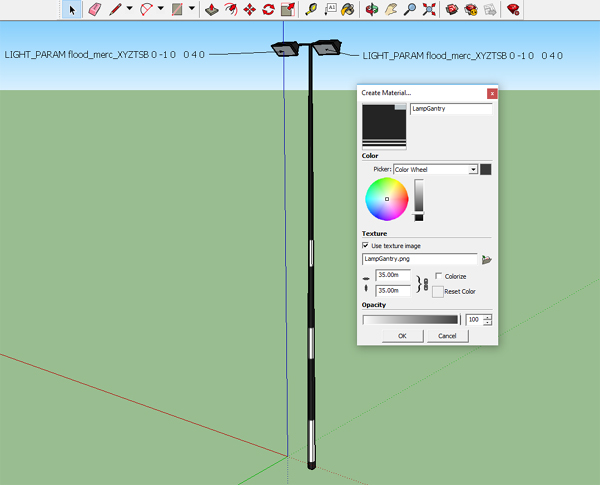
The .png texture file is a standard square with 3 white bands at the base. A pale grey square at the top is used to texture the lamp glass. This can be set to shiny by clicking on the lamp glass, right clicking and setting the glass to X-Plane/Shiny.
CAD orientation.
Knowing which direction is used to orientate lighting is important, otherwise you cannot control the direction of spill. Both Sketchup and Blender use the same configuration for direction and the light parameters need to be set to the direction in the program that created the model.
Solid
red X axis is East
dotted red X axis is West
Solid
blue Y axis is Up
dotted blue Y axis is Down
Solid green Z
axis is North dotted green Z axis is
South
Use the text tool
to set the light parameters. In
this case I am using LIGHT_PARAM
Flood_merc_XYZTSB.
Each one of the preset LIGHT_PARAM
settings has a different set of parameters.
In this case North South East and West apply to the axes of
the model and not the real coordinates.
Y - Up Down Lamp Direction -1=Down 0= Level 1=Up
Z - North South lamp Direction -1=North 0=Neutral 1=South
T - Throw in meters 0 is at the base of the lamp 30 is 30 meters north (or XYZ direction)
S - Size of Halo 1=Small 4=Large
B - Breadth of beam 0=no beam 1=full beam
When this model is saves as an X-Plane object, the file will have the location of the light position on the lamps embedded. Open the .obj file in Notepad and scroll down to the bottom to see the light parameters that have been inserted.
.......IDX10
265 268 265 266 271 270 269 272 269 270
IDX10
275 274 273 276 273 274 279 278 277 280
IDX
277
IDX
278
LIGHT_PARAM
flood_merc_XYZTSB
-0.0377
11.8424 -0.0249
0
-1 0 0 4 0
LIGHT_PARAM
flood_merc_XYZTSB
-1.4390
11.8590 -0.0450 0 -1 0
0 4 0
TRIS
0 522
# Built with
SketchUp 17.2.2555. Exported with SketchUp2XPlane 1.70.
The halo position is shown in RED above (inserted by SketchUp). The XYZ coordinates are shown in BLUE. The TSB parameters are at the end. These are set to give a halo only. Where there is more than 1 lamp shining, the light spill needs to be added as a separate markup coding. This is to avoid interference from multiple light spills crossing over. It keeps the software stress to a minimum.
To make the light
spill, an additional line needs to be added to the .obj file.
Full_Custom_Halo
will be on all of the time,
whereas Full_Custom_Halo_Night
will only come on at night.
Other settings are available.
LIGHT_PARAM
flood_merc_XYZTSB -0.0377
11.8424 -0.0249
0 -1 0 0 4 0
LIGHT_PARAM
flood_merc_XYZTSB
-1.4390 11.8590
-0.0450 0 -1 0 0 4 0
LIGHT_PARAM
full_custom_halo_night
-0.0377
11.8424 -0.0249
0.8
0.8
0.7
0.9
50
0 -1 0
0.2
The souce of the light spill is one of the lamps. The next parameters are the colour settings; 0.8 0.8 0.7 gives a light spill that is realistic and acceptable for this lamp set (pure bright white would be 1 1 1 ). 0.9 gives the intensity (0 is no light; 1 is bright light).
50 gives the radius of the light spill - This is the maximum distance in meters that the light spill will show (180 is the limit)
0 -1 0 are the XYZ coordinates for straight down.
0.2 is the semi width of the light cone. (0.5 is about 60 degrees)
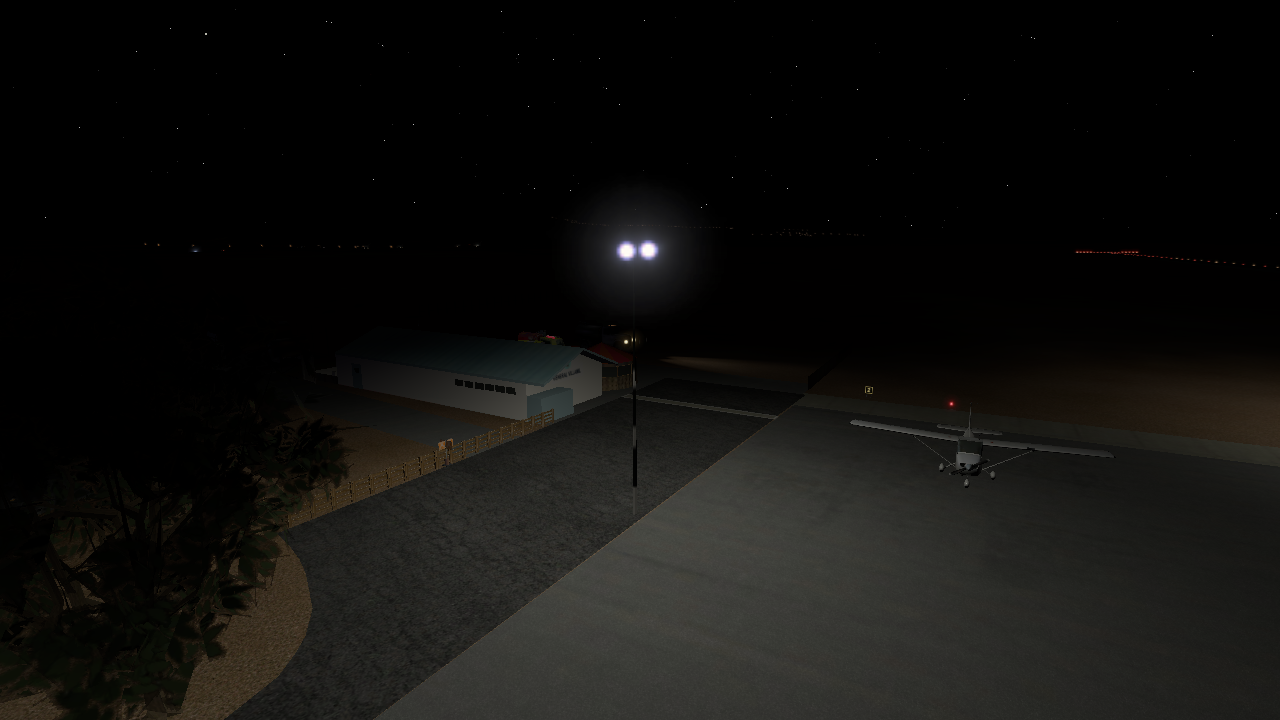
Position the lamp in your scenery using WED and place an aircraft nearby to see if it is working correctly
You can open X-Plane 11 and WED together and toggle between them. if you alter WED, then save and export scenery pack, you can toggle to X-Plane and - using the developer tag, reload scenery - to see how the changes have worked.
Play with the light settings to get the effect you want.

Top Tip
Use this technique to add red warning lights to buildings and obstructions. Download the following zip file to obtain a working example of Antenna Lights
.